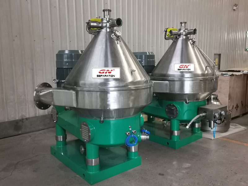
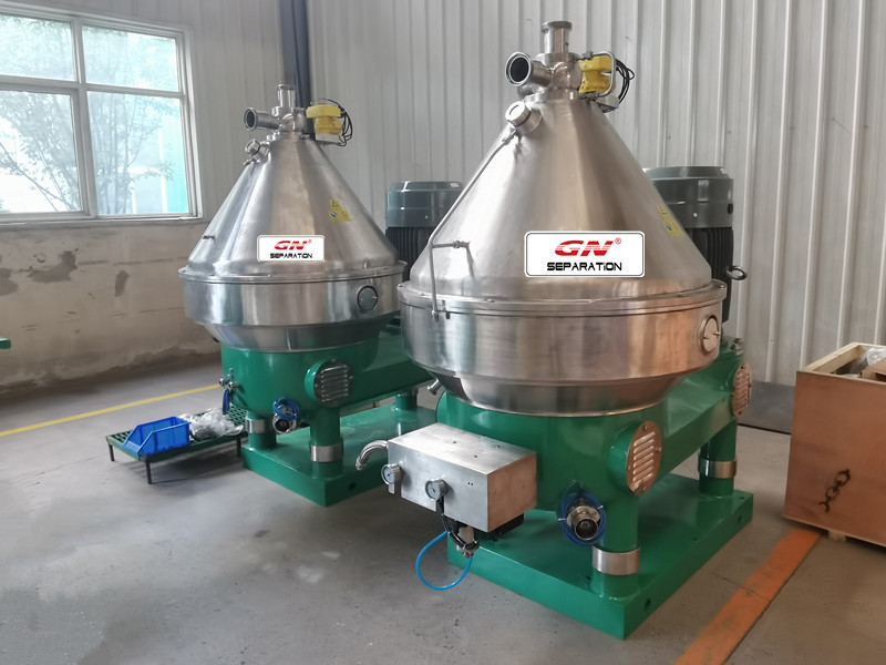
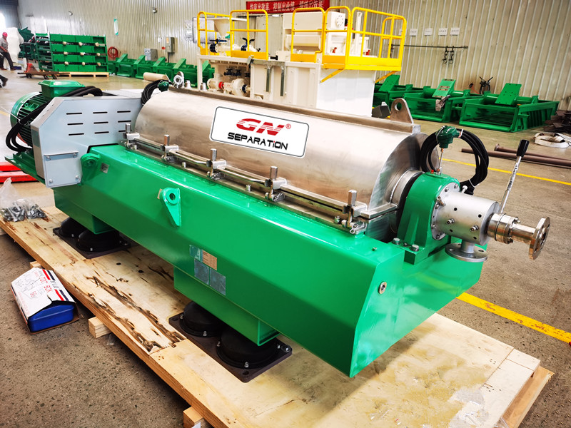
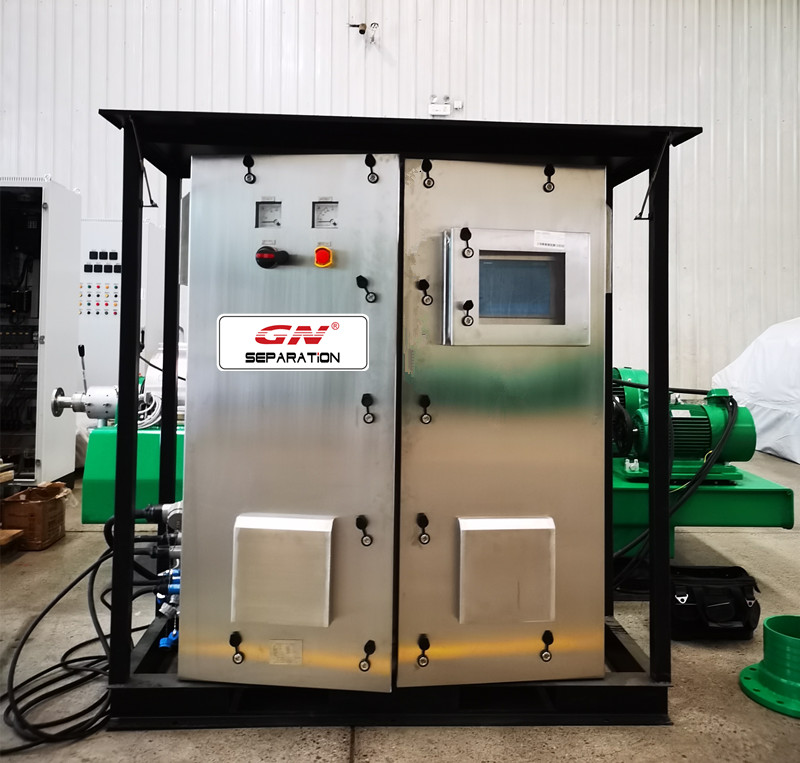
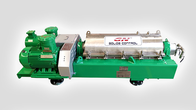
GN solid vacuum pump is called sludge vacuum pump, It’s a 100% pneumatic driving pump, which can do transfer work for solid and sludge, it will be connect with air compressor.
![]()
It’s a vacuum loading solids transfer pump, GN vacuum pump have 3 different model, GNSP-40, GNSP-20 and GNSP10, The maximum transport capacity of the three models for clean water is 10 cubic meters, 20 cubic meters and 40 cubic meters respectively. According to different material conditions, suction and discharge height and distance, the conveying capacity will be different. The max solid content is 80%, and the max particle size is 75mm for GNSP-40B.
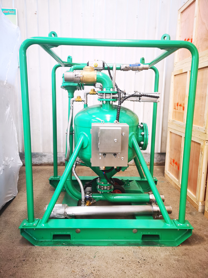
GN solid vacuum pump is often used to transport oily sludge to the treatment system.
GN solid vacuum pump has obtained European CE certification and ATEX explosion-proof certification.
For more information pls feel free t contact GN, suitable proposal will be sent you accordingly.